


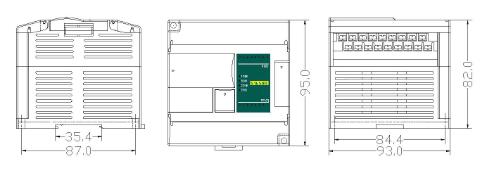
70*95*82 мм
| Позиция | Выходное напряжение | Выходной ток | ||||
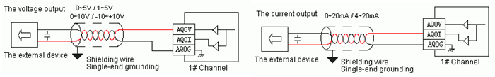
| Выходы | -10 В ~ +10 В | 0 В ~ +10 В | 0 В ~ +5 В | 1 В ~ +5 В | 0 ~ 20 мА | 4~20 мА |
| Разрешение | 5 мВ | 2.5 мВ | 1.25 мВ | 1.25 мВ | 5 мкA | 5 мкA |
| Сопротивление выхода | 1 KОм @ 10 В | >= 500 Ом @ 5 В | ||||
| Максимальный ток | 10 мА | |||||
| Время срабатывания | 3 мс | |||||
| Разрядность ЦАП | 12 бит | |||||
| Точность | 0.2% от диапазона | |||||
| Способ изоляции | Оптоизоляция аналоговой части (нет изоляции между входами) | |||||
| Потребление | 24VDC ±20%,100 мА(Макс) | |||||
| CR Number | Function Declare |
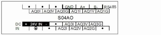
| S04AO | |
| 00H (Read only) | The low byte is the module code, and the high byte is the module version number. |
| 01H | Communication address |
| 02H | Communication protocol: The low 4-bit of the low byte:0 - N,8, 2 For RTU,1 - E,8,1 For RTU, 2 - O,8,1 For RTU,3 - N,7,2 For ASCII,4 - E,7,1 For ASCII,5 - O,7,1 For ASCII,6 - N,8, 1 For RTU |
| The high 4-bit of the low byte: 0 – 2400,1 – 4800,2 – 9600,3 – 19200,4 – 38400, 5 – 57600,6 - 115200 |
|
| 03H~06H | Extend module name |
| 07H~08H | Default IP address: 192.168.1.111 |
| 09~0AH (Read only) | Reserve |
| 0BH | High byte subnet mask (b3~b0,1 indicates 255, 0 indicates 0, for example subnet mask 255.255.255.0, b3~b0=1110), low byte reserved |
| 0CH~0EH (Read only) | Reserve |
| 0FH (Read only) | Error code: 0-Normal, 1-Illegal firmware identity, 2-Incomplete firmware, 3-System data access exception, 4-No external 24V power supply |
| 10H | The output value of channel 1 |
| 11H | The output value of channel 2 |
| 12H | The output value of channel 3 |
| 13H | The output value of channel 4 |
| 14H | The signal type of channel 1, note 2 |
| 15H | The signal type of channel 2, note 2 |
| 16H | The signal type of channel 3, note 2 |
| 17H | The signal type of channel 4, note 2 |
| 18H | Use the engineering value mark, note 6 |
| 19H | The lower limit in engineering value of channel 1 |
| 1AH | The lower limit in engineering value of channel 2 |
| 1BH | The lower limit in engineering value of channel 3 |
| 1CH | The lower limit in engineering value of channel 4 |
| 1DH | The upper limit in engineering value of channel 1 |
| 1EH | The upper limit in engineering value of channel 2 |
| 1FH | The upper limit in engineering value of channel 3 |
| 20H | The upper limit in engineering value of channel 4 |
| 21H | Power-off output mark, note 8 |
| 22H | The power-off output value of channel 1 |
| 23H | The power-off output value of channel 2 |
| 24H | The power-off output value of channel 3 |
| 25H | The power-off output value of channel 4 |
| 26H (Read only) | Channel indicator status, note 7 |
| 27H (Read only) | Reserve |
| 28H (Read only) | |
| 29H (Read only) | |
| 2AH (Read only) | |
| 2BH~2FH (Read only) |
1. Sampling frequency:0 - 2 times、1 - 4 times、2 - 8 times、3 - 16 times、4 - 32 times、5 - 64 times、6 - 128 times、7 - 256 times
2. Signal type:0 - [4,20]mA、1 - [0,20]mA 、2 - [1,5]V、3 - [0,5]V、4 - [0,10]V、5 - [-10,10]V
3. The signal type of thermal resistance:0 - Pt100、1 - Pt1000、2 - Cu50、3 - Cu100
4. The signal type of thermocouple:0 - S、1 - K、2 - T、3 - E、4 - J、5 - B、6 - N、7 - R、8 – Wre3/25、9- Wre5/26、10 - [0,20]mV、11 - [0,50]mV、12 - [0,100]mV
5. Disconnection alarm:Each bit indicates 1 channel, 0-normal, 1-disconnection
6. Use the engineering value mark:Each bit indicates 1 channel, 0-No, 1-Yes
7. Channel indicator status:Each bit indicates 1 channel, 0-off, 1-on
8. Power-off output mark:Each bit indicates 1 channel, 0-No, 1-Yes
9. The output flag while power supply lost: each bits signify 1 Channel ,0-No,1-Yes
| Характеристики | |
| Интерфейсы: | 1xRS485 |
| Наличие интерфейса RS-485 позволяет использовать модуль как удал | |
| Точки ввода/вывода: | 4AO |


 Антенны GSM/GPRS/LTE
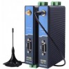 Сотовые GSM/GPRS-модемы
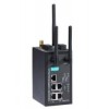 Сотовые GSM/GPRS-роутеры
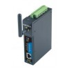 Сотовые IP-модемы с интерфейсом RS-232/422/485 и Ethernet
 Сотовые LTE-модемы
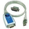 1-портовые преобразователи RS-232/422/485 в USB
 USB-хабы
 Многопортовые преобразователи RS-232 в USB в пластиковом корпусе
 Многопортовые преобразователи RS-232/422/485 в USB в металлическом корпусе
 Коммуникационное оборудование
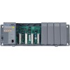 Корзины расширения
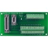 Платы и модули сбора данных для ПК
 Программируемые контроллеры
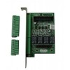 Системы захвата и передачи видеосигналов
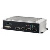 Advantech
  Cincoze
  DMP Electronics
 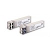 SFP модули для коммутаторов
 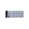 Коммутаторы с защитой от вибрации, от попадания пыли и влаги
  Коммутаторы с функцией Power Over Ethernet (PoE)
  Модульные коммутаторы Industrial Ethernet для стойки 19''
 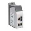 Модульные коммутаторы Industrial Ethernet на DIN-рейку
  Неуправляемые коммутаторы Industrial Ethernet
  Оборудование беспроводного Ethernet
 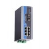 Управляемые коммутаторы Industrial Ethernet
  IP медиа телефоны
 IP телефония
 Microsoft Lync: телефоны и системы
 Готовые системы видеоконференцсвязи RealPresence
 Коммутация и распределение контента
 Программы
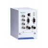 Видеорегистраторы
 Видеосерверы VPort
 Защищенные видеокамеры VPort


 закрыть